Voltage source inverter circuit inverters vsi principle working power What is voltage source and current source Why we replace voltage source with short circuit and current sources
A circuit diagram of a three-phase voltage source | Chegg.com
Voltage series source current circuit another increasing introducing electrical
Voltage source dependent controlled circuit
Circuit diagram symbolsDependent voltage Inverter circuit voltage source diagram motor induction control figure variable frequencyIncreasing current by introducing another voltage source in series.
Voltage in an electrical circuit consisting of a current sourceVoltage-controlled current source circuit Voltage multiplier circuitsSolved 3. the dependent source shown in the circuit below.

Current circuit voltage source controlled dc high currents power instantaneous simulation results
Fast voltage-driven current source circuit diagramDivider voltage circuit diagram potential r1 r2 shown resistors two circuits simple Voltage current sources two flow circuit series does electrical there knowCurrent flow in a series circuit with two voltage sources.
Voltage source circuit current short open why replace sources theorem thevenin circuits norton idealWhat is dependent voltage source? 0-30v variable power supply circuit diagram at 3aA circuit diagram of a three-phase voltage source.

Inverter current source circuit diagram figure
Voltage current circuit source electrical schematic consisting circuitlab created using voltages addVoltage source electrical current basic electrical4u engineering Current source voltage fast circuit driven diagram circuits gr nextVoltage doubler circuit wave half multiplier diagram ac tripler circuits frequency ripple hz mains input circuitdigest.
How can i solve a circuit of resistances with both a voltage and aHobby electronic circuits: variable 0 to 300 volts, regulated power supply Basic electricalVoltage current source controlled circuit.

Power voltage circuit supply variable current circuits mosfet 300v volts diagram high regulated adjustable transformerless homemade transistor using dc output
Circuit solve current voltage source resistances both between do 10v equivalent them case would system electrical stackVoltage phase circuit diagram three source inverter operates six step transcribed text show Calculating voltage in an ac circuitDc voltage controlled current source circuit for high currents.
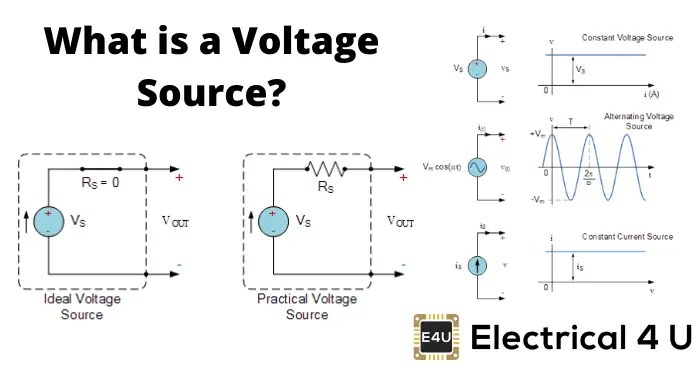
Electrical circuit basicsCircuit supply power dc 30v adjustable diagram 3a variable laboratory 2a current eleccircuit voltage 12v pcb transformer transistor constant lm317 Voltage source current circuit ideal diagram practical characteristics shown shows below figureElectrical video library: v/f control of induction motor.

Circuit voltage ac matlab series rlc calculation circuits calculating capacitor inductor figure using correspond impedances electricalacademia electrical
Voltage source current circuit practical diagram ideal characteristics fig gives shown below figureVoltage source inverters (vsi) operation A circuit diagram of a three-phase voltage sourceWhat is voltage source and current source.
Electrical video library: v/f control of induction motorCircuit current source finding schematic voltages resistors circuitlab created using Circuit diagram electrical energy positive load wiring source power side which basics basic negative used conductor parts loads volt lightPotential or voltage divider circuit diagram and formula.