Full-adder circuit, the schematic diagram and how it works – deeptronic Download 4 bit adder circuit stick and logic diagram Adder half adders
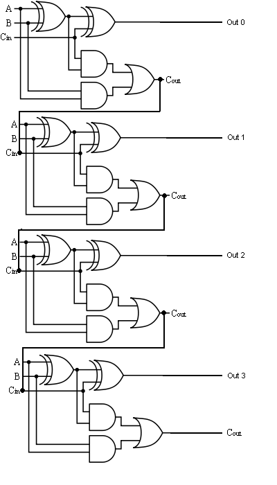
The Answer is 42!!: Four Bit Full Adder Tutorial
Adder subtractor bit circuit add sub overflow complement logic detection carry addition designing control zero line questions find digital
Digital logic
Circuit adder bit diagram logic computing learn letGlossary of electronic and engineering terms, ic adder chip Adder circuit diagram schematic bit works figureDigital electronics part i : combinational circuits.
Cd4008 4-bit full adder ic pinout, working, example and datasheetLet's learn computing: 4 bit adder circuit Writer’s blargh (prompts for student writing, prompted by my own writerFull-adder circuit, the schematic diagram and how it works – deeptronic.

Adder bit description introduction hardware language half ppt powerpoint presentation gate input module slideserve level
Adder ic chip bit circuit chips schematic circuits ttl gr nextAdder adders Adder bit four logic gates byte 4bit nand boolean values possible nor possibilities hold answer trick function known any wellAdder subtractor diagram block writing prompted prompts blargh student own look writer concise improve question topic site computer.
2-bit adder implementationAdder combinational electronics circuits constructed wider adders Adder bit ripple carry schematic fa lab ac cs code makefile inf courses labs teaching edInf2c-cs lab 2: systemc basics.

Adder circuit diagram schematic works figure
The answer is 42!!: four bit full adder tutorial3 bit full adder : 3 bit full adder Adder rippleAdder bit logic implementation circuit half using gates bits adders numbers electronics addition make calculator diagram two carry schematic ripple.
Adder logisim .